TEXAS, LIKE MANY OTHER SOUTHERN STATES, has seen substantial population growth recently.
This growth is one of the key drivers for expanding Inter- state capacity, particularly in cities like Waco. I-35 meanders through the east Texas city, home of Baylor University, and the Waco District of the Texas Department of Transportation (Tx- DOT) wanted to do more than just add capacity with the $17.3 million IH-35 frontage road bridge project. It wanted to make a statement. By pioneering the application of extradosed bridges in the U.S., the city of Waco and TxDOT did just that (see side- bar for a description of extradosed bridge design).
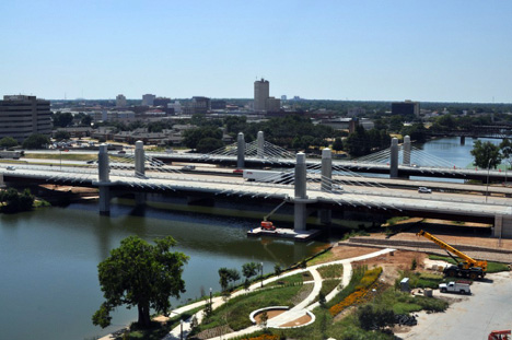
Spanning the Brazos River and parallel to the existing main- line I-35 bridges, the new IH-35 frontage road extradosed bridges are 620 ft long and are the first extradosed cable-stayed bridges in the U.S. to use a steel superstructure. Traffic on each bridge is one way, with the new bridges placed to the outside of the main-line bridges. The existing mainline bridges will soon be replaced with new steel box-girder bridges as part of the IH-35 corridor improvements. In the final configuration, both the northbound and southbound frontage road bridges will be separated horizontally some 60 ft from the corresponding mainline bridges.
The roadway for each frontage road bridge carries three traffic lanes with shoulders, as well as a 10-ft, 6-in.-wide sidewalk for pedestrians and cyclists. In addition, scenic overlooks providing unobstructed river views are incorporated into the pylons to enhance the bridge experience for pedestrians. Each of the new twin structures is a three-span bridge with a 250-ft center span and 185-ft side spans. Matching the span configuration of the proposed new mainline bridges, this configuration aligns the piers within the river for all the bridges in their final condition.
Each bridge’s superstructure consists of 6-ft, 6-in.-deep steel trapezoidal box edge girders, 3-ft, 6-in.-deep steel-plate I-girder floor beams and 10.5-in. cast-in-place concrete deck. Transverse floor beam spacing varies from 13 ft, 3 in. in the end region of the side spans to 15 ft in the regions near the pylons. The trapezoidal box edge girders are composed of 3/4 inch web plates, with 2 inch wide top flange plates and a 5-ft-wide bottom flange plates. Top flange plate thickness varies from a typical 1 in. up to 3 in. for the regions over the bearings at the pylons, and the bottom flange plate varies from a typical 1-1/4 in. to 3 in. over the pylons. The box edge girders are continuous for the entire length of the bridge, supported on single disc bearings at the abutments and pylons. The transverse I-girder floor beams consist of 1/2 in. web plates with 1-ft, 6-in.-wide by 1-in.-thick top and bottom flange plates. Each H-shaped pylon consists of two 9-ft, 3-in. by 9-ft, 3-in. rectangular towers with a haunched 5-ft, 3-in.-wide crossbeam that supports the superstructure.
The project team chose a steel-girder composite cross section for the design. While a concrete cross section is typical for extradosed bridges, TxDOT preferred steel girders with concrete decks because of its familiarity with this superstructure scheme. In addition, structural engineer AECOM evaluated the use of a cast-in-place concrete box girder superstructure but determined it to be economically untenable. In addition, the project team used a steel trapezoidal box section for the edge girders, rather than a steel-plate I-girder section more commonly used on composite cable-stayed bridges, in order to provide greater superstructure stiffness and less reliance on the cable stays. The team also wanted to visually match the new mainline bridges, which will be steel box-girder bridges. The cable system consists of a single plane of five cable stays at each pylon supporting the edge girders (a total of 20 stays for each bridge). The cable stays are anchored at the deck level to the web of the steel box girder and pass through cable saddles in the pylons. With 12 strands per cable, the stays are composed of 0.62-in.-diameter, seven-wire, low-relaxation strands. For improved corrosion resistance, each strand is coated with wax and encapsulated inside high-density polyethylene (HDPE) sheathing. The strand-bundled stays are further protected by an outside HDPE pipe.
Since an extradosed bridge has two load-carrying systems, cable support can be provided for only a portion of the span. Consistent with the geometry of many extradosed bridges, the final stay for the IH-35 frontage road bridges is offset from the pylon by approximately 20% of the main span. From this first stay, the cable support points are spaced 14 ft, 9 in. along the edge girder, for a total of 59 ft. This results in approximately 50% of the main span being cable supported, which is consistent with most existing extradosed bridges that have cables distributed across approximately 60% of the span.
Due to the use of the relatively more flexible steel superstructure (supported at the pylons by bearings), the resulting liveload stress range in the stays was greater than the Post-Tensioning Institute’s (PTI) limit that would allow the stays to be designated as low-fatigue. The stress variation caused by live loads (AASHTO HL-93 live load with no pedestrians) varied up to approximately 15 ksi versus the 6.75 ksi limit for the stays to be considered extradosed. So the stays were designed accordingly, using the same provisions in the PTI manual as for conventional cable-stayed bridges.
A complete erection scheme was also developed during the design of the bridge to inhibit both cracking of the concrete deck during construction and slippage of the stay strand through the saddles. Further, the cable-stay and saddle system chosen was specified to allow for the installation and replacement of stay strands on an individual strand-by-strand basis. This was no small consideration since the ability to replace strands on an individual basis will allow future bridge maintenance workers to pull and inspect strands without needing to replace the entire stay. Stay strands will be placed within individual holes in the cable saddle, significantly reducing the risk of fretting corrosion and facilitating strand-by-strand replacement. Although using saddles is a common practice elsewhere in the world, it is relatively new in the U.S. and only a few bridges have been designed with this system.
Not only was this the first use of a steel extradosed bridge in the U.S., but the project also had to content with heavier than usual deadline pressure thanks to Baylor announcing that it would be constructing its new Lane Stadium football facility adjacent to the bridges, with an opening date of August 31, 2014. Nevertheless, the bridges were delivered 4.5 months ahead of the original schedule and opened to traffic that July.
Owner
Texas Department of Transportation, Austin
Designer
AECOM, Glen Allen, Va.
Contractor
The Lane Construction Corporation, Lorena, Texas
Steel Fabricator
Hirschfeld Industries, San Angelo, Texas
Detailer
abs Structural Corporation